ZSWatch Assembly
This guide shows how to assemble the ZSWatch PCB and parts in the 3D-printed case.
Not applicable to the WatchDK.
What You Need
| Item | Notes |
|---|---|
| ZSWatch PCB | With display and vibration motor. |
| Battery | 3.7 V LiPo, 402030 (200 mAh), with a 2-pin 1.25 mm pitch plug that fits the Molex PicoBlade connector (53261-0271) on the PCB. Links to tested batteries will be added here once the watch PCBs are available. |
| Printed case parts | Housing, back plate, insert, 4 buttons and 4 button holders. With the heart rate extension board: the heart rate back plate and its center cover instead of the normal back plate. See Printing the Case. |
| 2 × M2 screws | 3-4 mm long. |
| Watch strap | 22 mm quick-release strap. |
| Super glue | Only for the heart rate extension board. |
The photos show an earlier PCB where the battery is soldered directly to the connector. On the final PCB the battery has a proper plug, and the connector sits a little further out on the bump of the PCB. The assembly is otherwise the same.
Printing the Case
The STEP and STL files are in the Watch-3D repository.
| File | Qty |
|---|---|
clock_housing.stl | 1 |
bottom.stl | 1 (without heart rate extension) |
bottom_hr.stl + bottom_hr_center.stl | 1 each (with heart rate extension) |
insert.stl | 1 |
button.stl | 4 |
button_holder.stl | 4 |
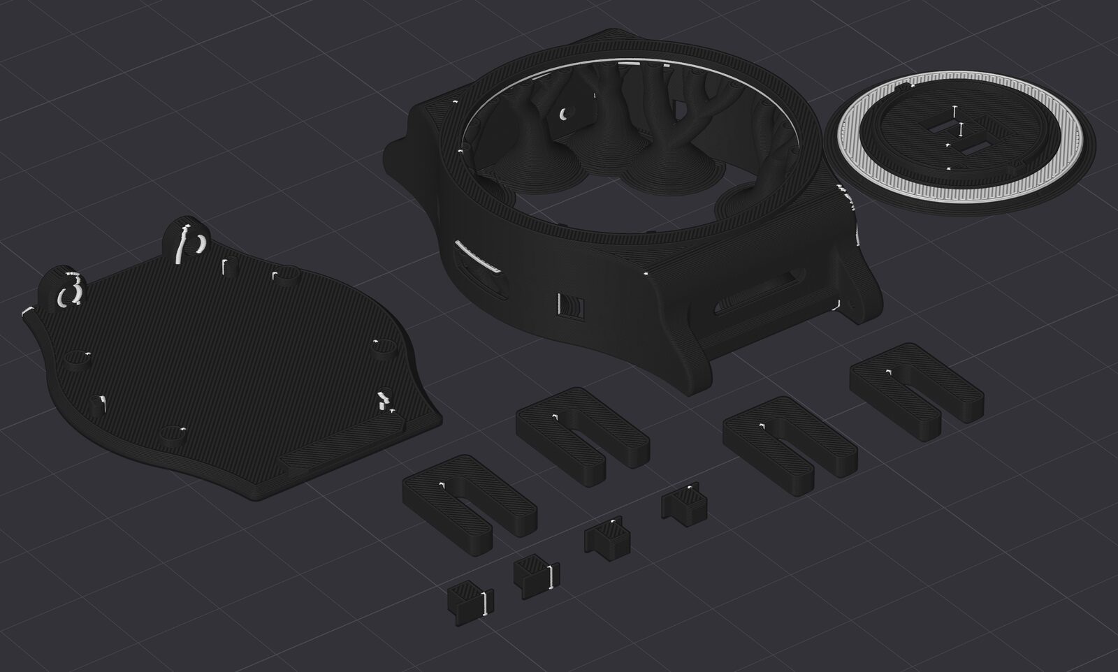
- Layer height: 0.12 mm is tested. Higher works too.
- Orientation: as in the slicer screenshot above.
- Supports: needed for the housing and the heart rate back plate. A different material for the support interface, such as a PLA support material, makes the supports easier to remove, but is not required.
- Finish: ironing gives a nicer top surface. The default ironing settings in Bambu Studio work well.
- Button holders: they should fit snugly around the buttons. If they are loose on your printer, scale them down slightly.
Walls are thin and there is no infill, so the default wall and infill settings are fine.
Step 1 - Check the Parts
Lay out all parts and check that nothing is missing.
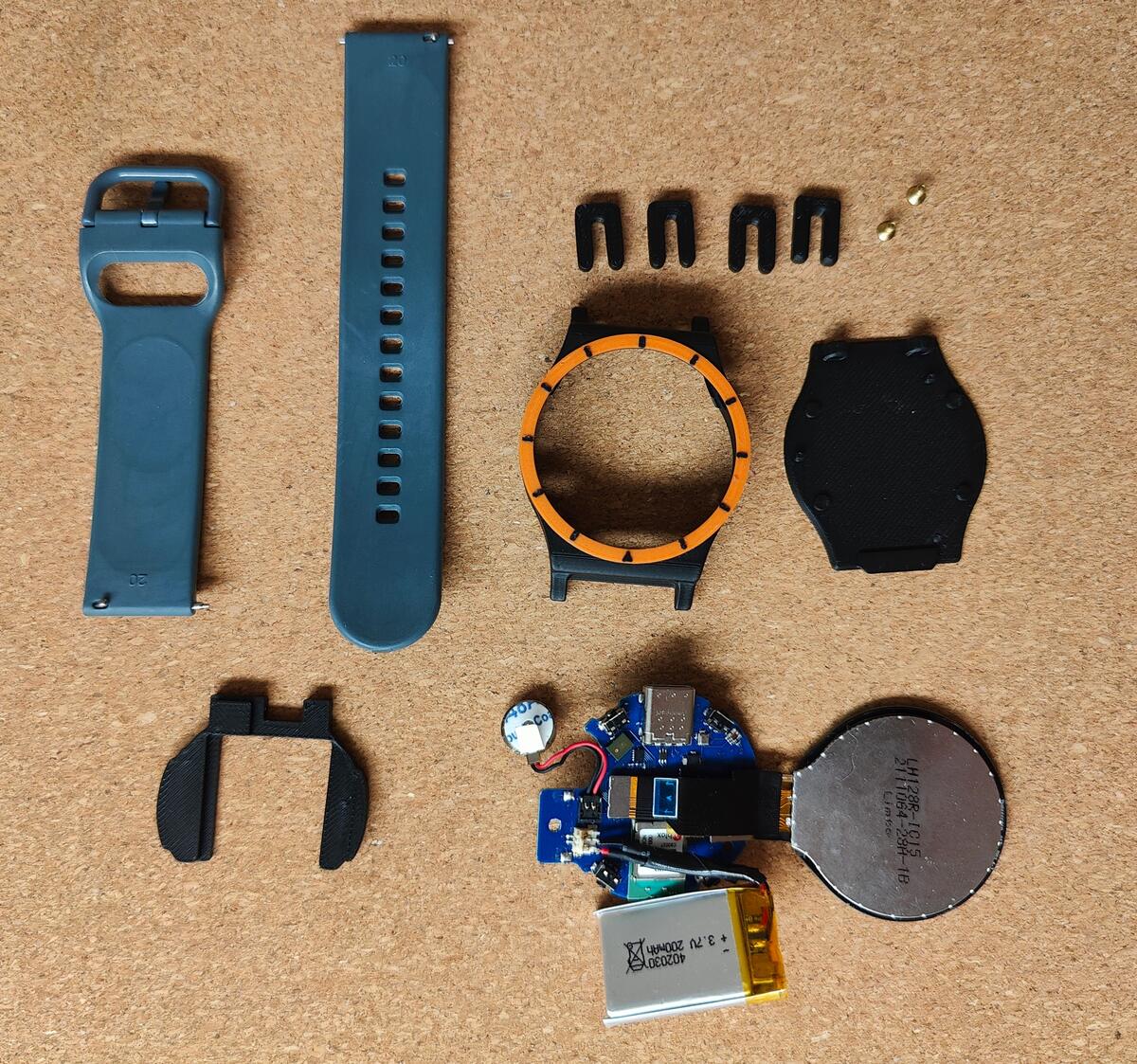
Step 2 - Connect the Vibration Motor
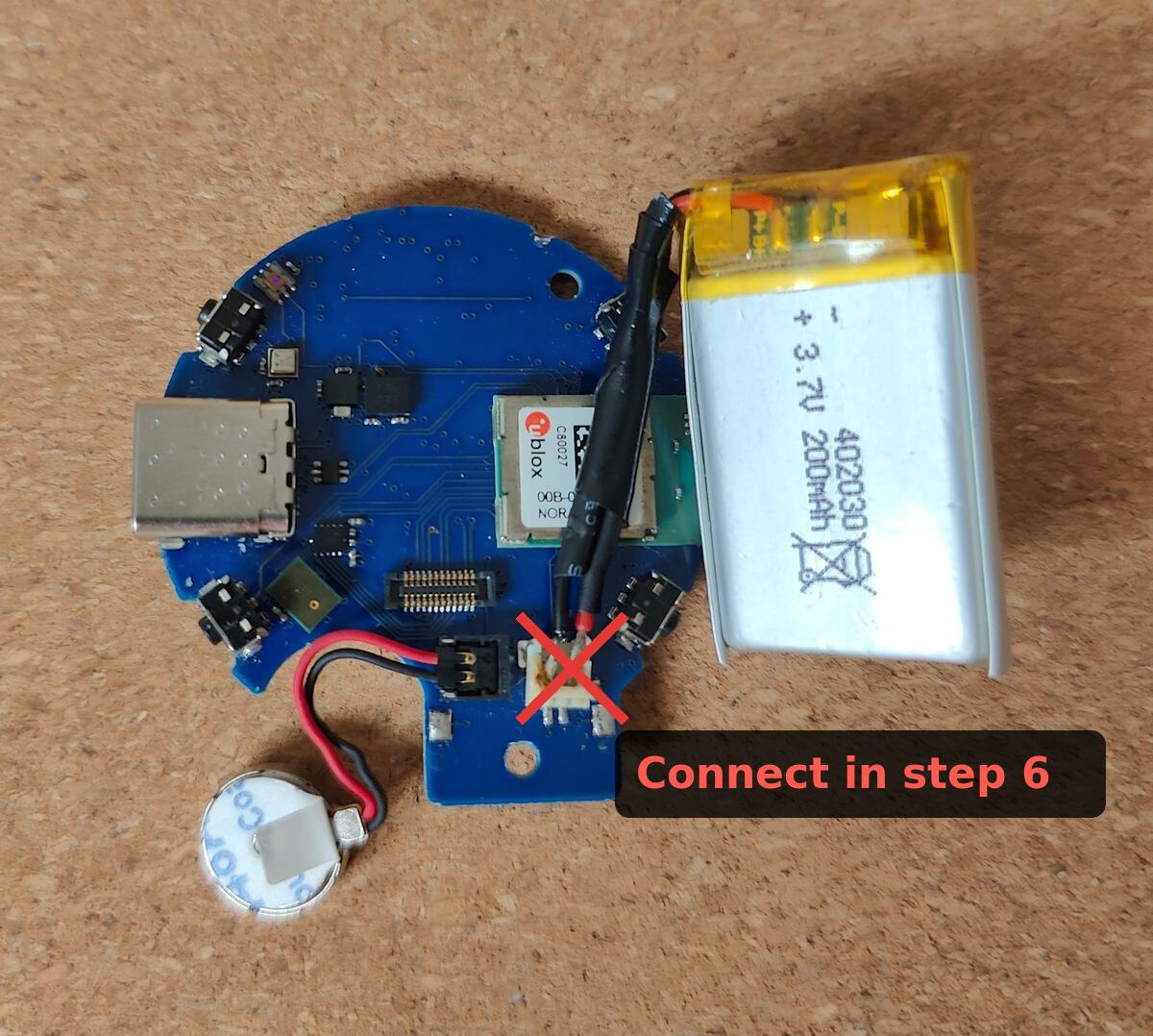
Plug the vibration motor into the PCB. Keep the protective film on the adhesive side of the vibration motor for now.
Wait with the battery until Step 6, after the display is connected. The photo shows the battery already connected, but connecting it last avoids any risk of a short if the display is plugged in wrong.
Step 3 - Insert the Display
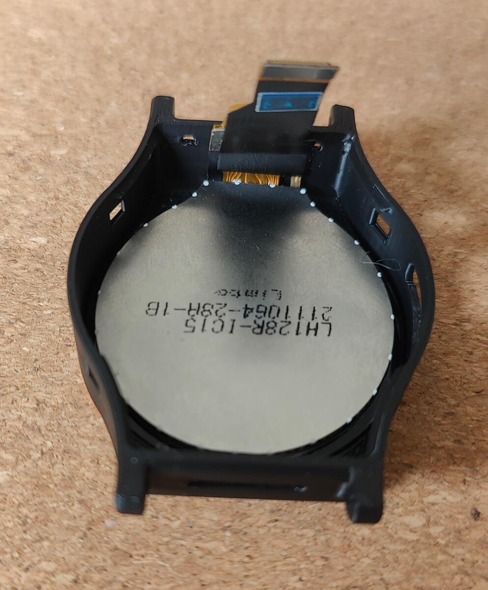
Place the display face down in the housing. It only fits one way. Make sure it sits flush against the front of the housing; remove any support material left in there first.
Step 4 - Fit the Buttons
Push a button into one of the side holes from the inside.
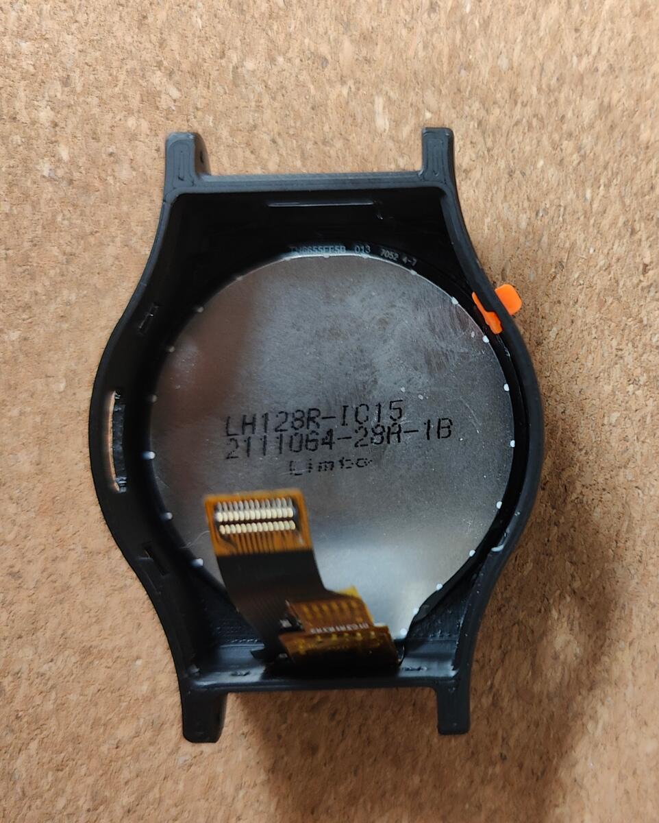
Slide a button holder over it from the outside. The holder only keeps the button in place during assembly.
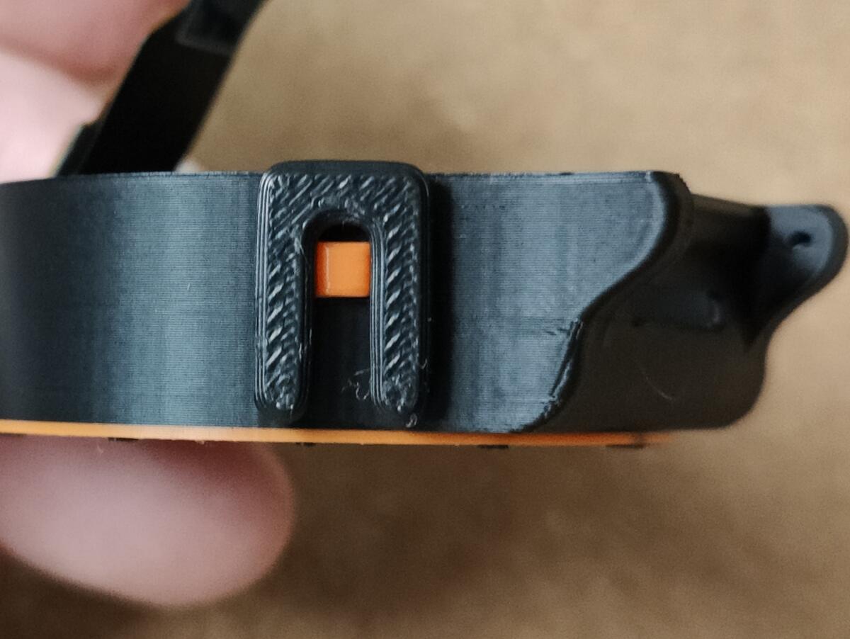
Repeat for all four buttons.
Step 5 - Place the Insert
Put the insert on the back of the display. All four buttons and button holders should now be in place.
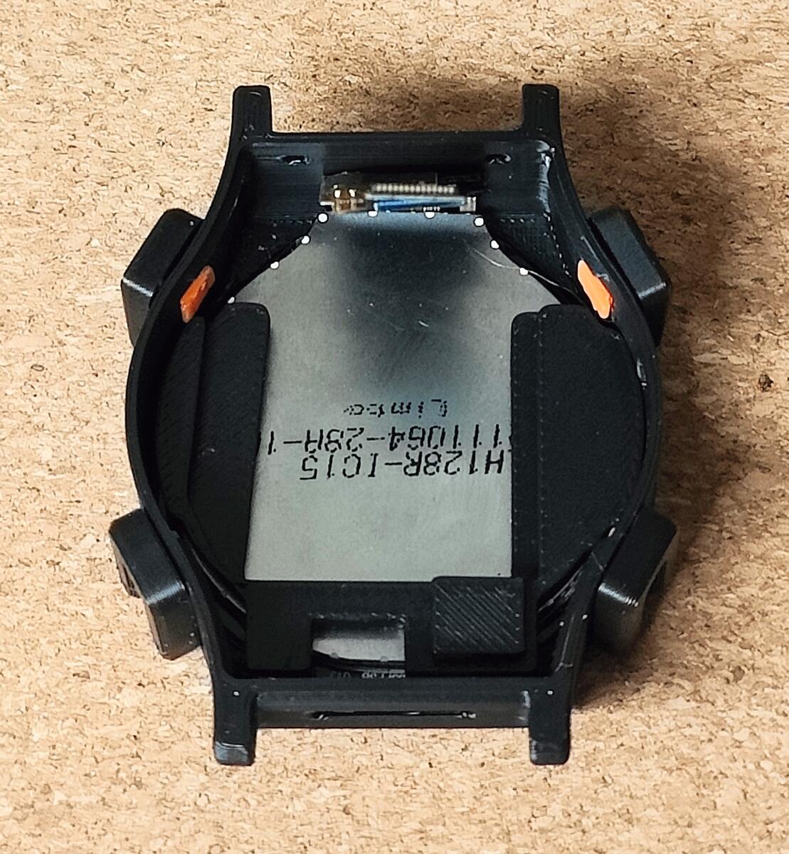
Step 6 - Connect the Display and the Battery
Connect the display flex cable to the connector on the PCB. Press straight down until it clicks. Then connect the battery.
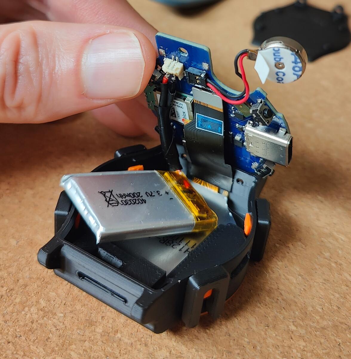
Place the battery in the insert.
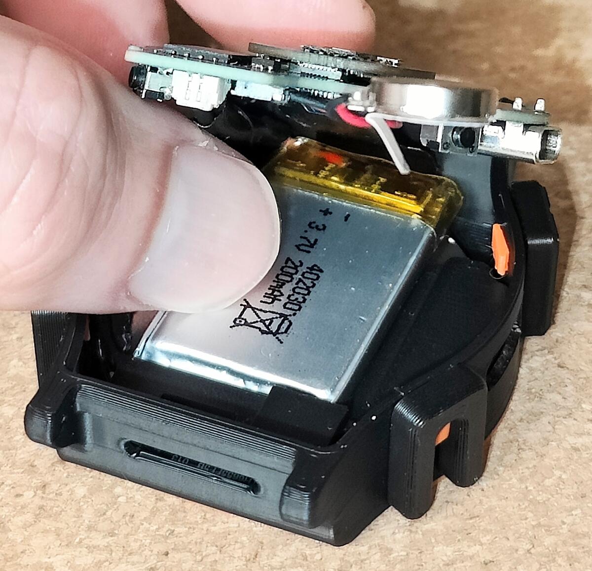
Step 7 - Fold In the PCB
Start with the USB-C connector: put it into its hole in the housing and push it in. Then push the PCB down until it lies flat in the housing.
The buttons on the PCB need to clear the edge of the printed buttons. With the USB-C connector in its hole, a little force pushes the PCB past them.
If the PCB does not go down flat, the battery wires are probably in the way. Push them a little to the side and try again.
Step 8 - Stick the Vibration Motor
Remove the film from the vibration motor and stick it in its pocket on the insert.
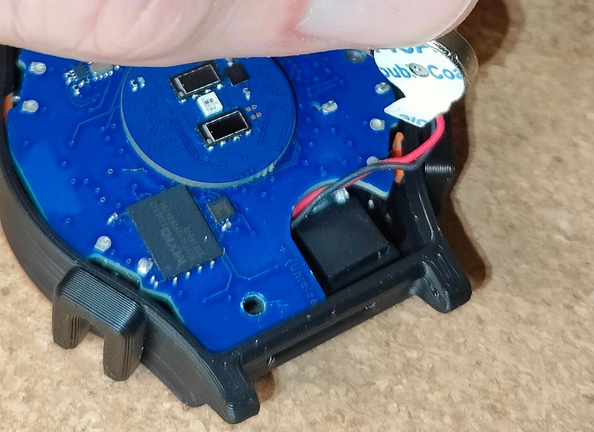
Step 9 - Close the Back
The photos show the version with the heart rate extension board. Without it, the process is the same; the back plate just has no hole in the middle.
Slide the tab at the bottom of the back plate into the slot in the housing first. Then lower the back plate until it lies flat against the edges of the housing.
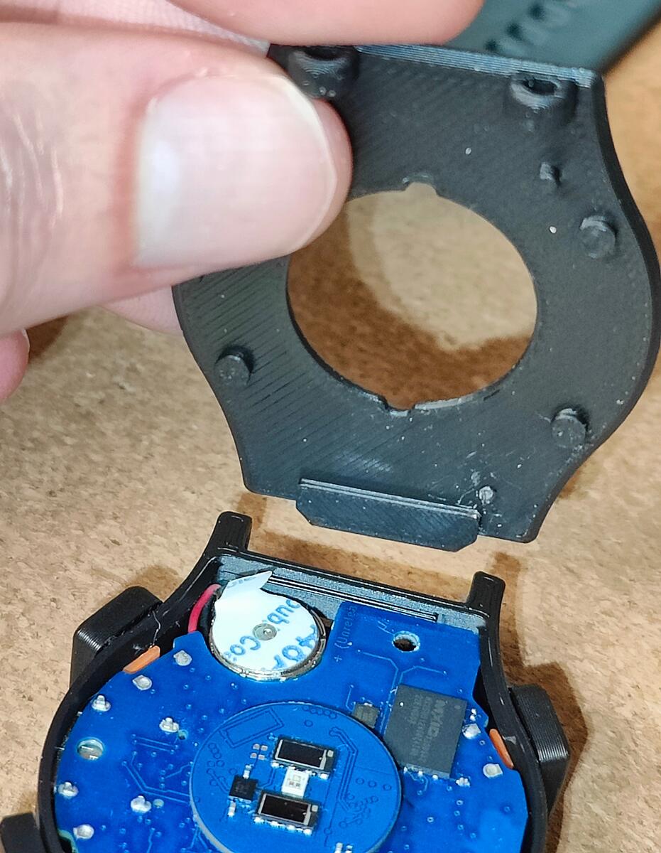
Screw the two M2 screws into the holes at the bottom of the housing.
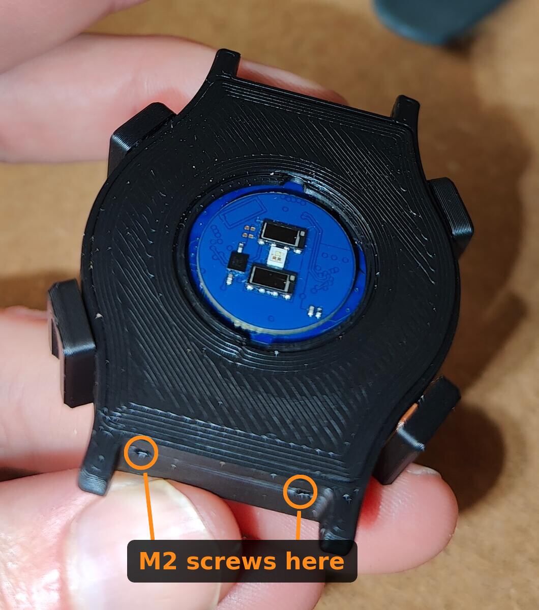
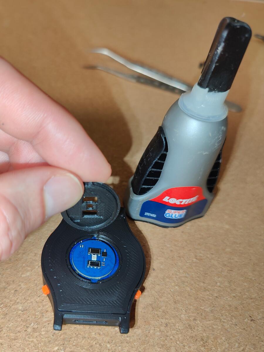
Step 10 - Heart Rate Extension Only: Glue the Cover
Skip this step if you do not have the heart rate extension board. We are still fine-tuning this part, so it may change.
Glue the center cover (bottom_hr_center.stl) into the hole in the heart rate back plate with a drop of super glue. The back plate and the cover both have slots, so the cover aligns by itself.
Step 11 - Attach the Strap and Power On
Attach the strap to the lugs. Connect USB-C to charge and power on the watch, then follow the Quick Start to update the firmware and upload image resources.